Mounting A goshawk
The Stand
Final details first…
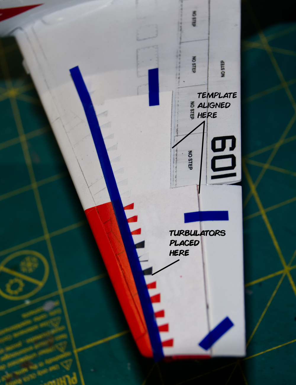
The Goshawk was almost done and this point and finishing was the hardest hurdle yet. Partialy because my patience for the project was nearly exhausted and also the finishing details were rather finicky. The first items to be tackled were especially tedious, the turbulators on the top of the wing. These were originally molded to the upper wing kit parts. As molded the turbulators were removed because they were out of scale, would have been lost in the wing shape modifications, impeded decal application and panel line work, etc. Replacement parts were cut from 0.003” tooling aluminum. A printed template was glued to the aluminum and the parts were cut out with a scalpel then folded at 90° angle. The appropriate number parts were painted orange and white. Application to the turbulators to wing was a bit of an effort. In order to get the correct spacing and placement on the wing, portions of the wing drawing were printed to regular copy paper as a base to cut a template. I carefully cut the each turbulator location at the rear and outboard edge, so 90° edges were formed where the bent edge and rear of the turbularor can be aligned. The flap and aileron locations were also cut from the paper template so it could be aligned with the flap and aileron to ensure the proper placement of the turbulators on the wing. The painted turbulators were then glued to the wing with cyanoacrylate glue.


The painting was finished off next. The final coat of semigloss clear was applied, I used Alclad Lacquer. Then the anti-glare panel on the nose and the non skid panel on the top of the left intake. These areas were painted last and not clear coated so I could retain he flat sheen. It was a little tricky to lay down masks clear of the decals, to ensure the decals were not puled off with the masking.
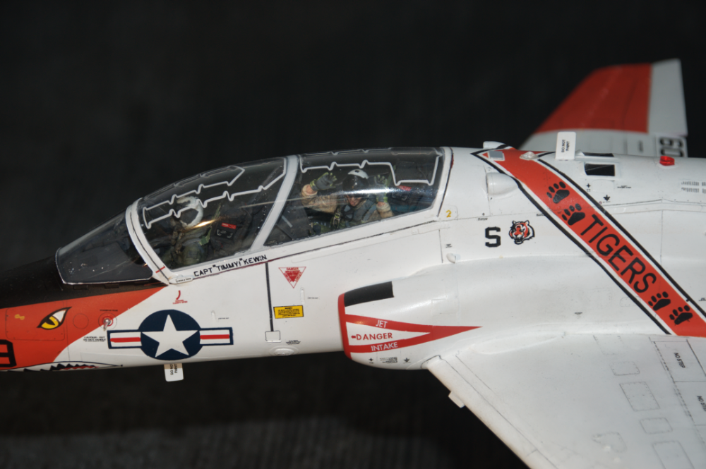
Final details consisted of an angle of attack (AOA) and total air temperature (TAT) probes, a vent tube, lights and the arresting hook. The AOA probe was turned from aluminum. The TAT probe was carved from sheet styrene. The vent was a kit part painted silver. Upper and lower red beacons and white strobe were cut from appropriate colored toothbrush handle, by way of my CNC mill. The lights were polished and coated with clear acyclic floor “polish”. The hook was a 3d printed part painted white and black strips of decal cut and applied for the stripes.


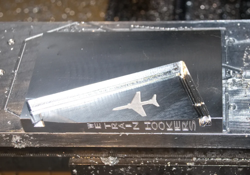
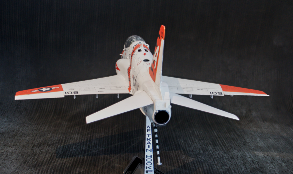
The stand was milled from aluminum. A couple of blocks of stock were squared up and trued on all six sides. The base was cut in a roughing pass and several finishing passes. One established the faceted center section and horizontal surfaces. The next pass created the 0.005” pocket and lettering. Finally a scribe pass the bisect the faceted center section. The base was then cut off the remaining stock. The post was a little more complicated. The spine of the post was tackled first with the engraved lettering. Then the left and right sides were milled out in the same manner as the base. Polishing of the parts followed, by filing off milling marks, followed by many progressively finer grits of sand paper and rotary tool with buffing wheel and polishing compound. The base was modeled after an actual squadron patch. The patch had a half blue and half orange background at its center. It was my original plan to paint the center section of the base with these colors. After further thought, that much color would distract from the model. So the center section was given a brushed effect with each half “brushed” at 90° from each other. The engraved sections were then filed with automobile epoxy direct to metal primer. The paint was then sanded and polished flat to reveal the lettering in the base and level to aluminum surface of the post. A separate sheet aluminum flange was cut to fit the triangle shaped peg at the top of the post and curved to match the model contour. A triangular hole was cut into the model and paint scrapped of the surface to match the flange. I used JB Weld metal filled epoxy to mount post to the base, and also the post, flange and model together.


Finished Model…


Of note, I decided to name the model, “A Student’s Revenge.” The name comes from the configuration of the flying surfaces; that will be my only hint about where the name comes from.
That ended the construction of the project. It’s not a show winner, there are plenty of buggers that would need to be fixed. My purpose in building this conversion was about finding new solutions to problems and trying new techniques. For example, the aluminum stand was a big hurdle and this is the first kit model where I used vinyl surface details. A boat load of CNC and 3d printed items, though not new to me in my scratch build work, adapting them to a kit model was new to me.
I hope you enjoy this series. There’s a little more to go. I have a differences article that will identify all the differences between a Hawk and Goshawk, as an information article or build guide should you want to build a Goshawk. Also I’m looking into ways to make the plans and conversion parts available.
Thanks for watching,
Timmy!
Written and performed by,
Timmy!
December 4, 2018